Our Eigth Lab: Using an OLED Digital Display
We will use the SSD1306 OLED display in this lab.
-
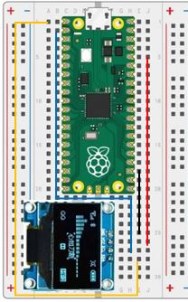
Insert the display into
f25, f26, f27, and f28 -
Using one of the jumper wires, insert one end to
i25and the other end intoi18 -
Using another jumper wire, insert one end to
j26and the other end intoj5 -
Using another jumper wire, insert one end to
h27and the other end intob2 -
Using another jumper wire, insert one end to
i28and the other end intoa1 -
When you are finished, your breadboard should look similar to the image below (Note: your wires may be different colors)
Working With the SSD1306 Display
-
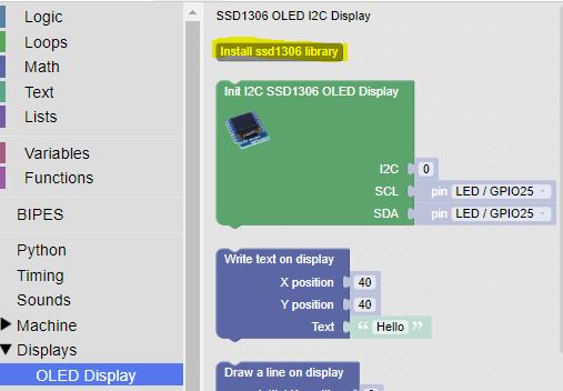
We'll need to add the SSD1306 Library to our microcontroller. This can be done through the Install ssd1306 library button in the Display OLED Display section:
-
Our display uses an Inter-Integrated Circuit (I2C) interface. The I2C interface was first developed by Phillips Semiconductor in 1982 to facilitate serial communication between devices.
-
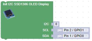
Initialize the display with the Init I2C SSDD1306 OLED Display block, taking care to set I2C to 0, SCL to Pin 2, and SDA to Pin 1.
-
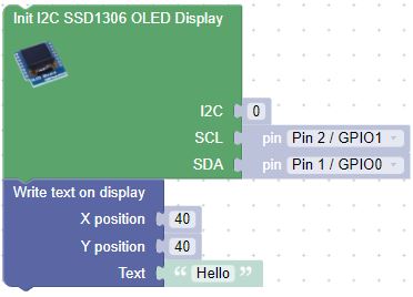
Now we can write "Hello" to the display with the Write text on display block
Challenge
-
Start by writing your name to the display at the top left corner (0, 0).
-
Pause for 1 second
-
Clear the screen (use the Clear OLED Display block)
-
Move your name down and to the right
-
Pause again
-
Continue moving down and to the right until you get to the bottom or the right edge of the screen.