Our Fifth Lab: Using an Analog to Digital Converter (ADC)
Parts for this Lab are as follows:
-
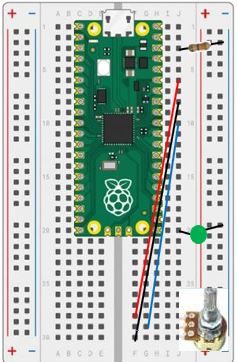
We need a single LED and resistor for this lab. As a reminder for the setup:
Insert the Anode(+) lead into j20Insert the Cathode(-) lead into the Ground(-) railInsert the resistor leads into j3 and into the Ground(-) rail -
We will also use a potentiometer (variable resistor).
- Insert the pins of the potentiometer into
j30, j29, and j28 - Using one of the jumper wires, insert one end to
f30and the other end into thej8 - Take a second jumper wire, insert one end into the
g29and the other intoj10 - Using a third jumper wire, insert one end into
f28and the other end intoj6
- Insert the pins of the potentiometer into
-
When you are finished, your breadboard should look similar to the image below (Note: your LED and wires may be different colors)
What is Analog to Digital Conversion (ADC)?
The microcontroller has the ability to convert an analog voltage (a voltage anywhere between 0 and ADC_REF volts) to a corresponding digital (0 to 65535) reading. We can then use that potentiometer to vary the input to one of the ADC pins by turning the knob clockwise and counter clockwise.
Note the use of the special voltage pins (ADC_REF and AGND): The supply voltage is filtered, since we want to exclude ripples due to the chip’s internal clock.
The object of this lab is to have the external LED start out on. Then, slowly dim the LED using the potentiometer. Once the LED is off, slowly bring it back to full brightness. Continue until you stop the program.
-
Reading from the ADC pin is accomplished by the following block from the Machine In/Out Pins:

Challenge
Now that we know how to read data from the potentiometer via the built-in analog to digital converter, we want to use that data to vary the brightness of the LED.
Remember that the brightness of the LED can be set by changing the duty cycle of the pulse width modulation, just like we did in the previous lab.