Breadboard
We use standard solderless small breadboards in our labs. The breadboards have holes that are spaced 1/10th of an inch apart which is a standard for most electronics in the US.
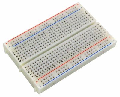
Our breadboards are usually 1/2 size with 400-ties. They have a central trough and power rails on the left and right edges.
Breadboard Regions and Connections
Learning how a breadboard works is critical for building our projects. In the figure above you will see that there are two types of regions of the breadboard
-
The side regions are called the power distribution rails. They are similar to power lines that reach across our projects.
-
The central region is called the row connector region. In this area the horizontal rows are all connected inside the breadboard. Within any row, columns a, b, c, d and e are all electrically connected. Within any row, columns f, h, i, j, and k are also electrically connected. However, there is a gap between columns e and f called the center gap or component slot that parts are usually placed over. Components like buttons will have their pins straddle the component slot.
Microcontroller Placement on Breadboard
For our labs we place the microcontroller board so that pin 1 of the microcontroller is in row 1 of the breadboard as in the image below.
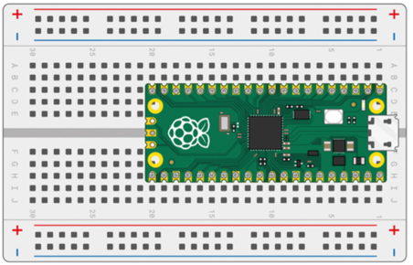
This means that the GND connections to the microcontroller are always in rows 3, 8, 13 and 18 on both sides of the breadboard. One of the ground pins can be hooked up to the vertical blue power rails on either side of the breadboard.